
3D MODEL
MAIN MENU
WIRING DIAGRAM
UPDATE FIRMWARE
ANDROID APP
3D MODEL
For those interested in customizing or exploring the physical dimensions of the UPAN Controller Generation 3.0, we have made a 3D model of the enclosure available for download. This model, created in Autodesk Fusion, can assist in understanding the layout and designing any necessary mounts or modifications.
Access the 3D model by following this link: Download 3D Model
Please note, the link will direct you to a resource where you can easily download the model for your use. The model provides a detailed representation of the enclosure, allowing for precise customization and integration.
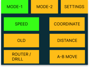
MAIN MENU
MAIN MENU
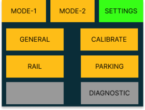
SETTINGS
SETTINGS -GENERAL
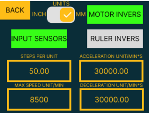
UNITS: Toggle the measurement units between inches and millimeters for machine operations.
INPUT SENSORS: Access end switch
MOTOR INVERS: Reverse the direction of motor operation if necessary to ensure correct movement.
RULER INVERS: Invert the readings from the ruler.
STEPS PER UNIT: Set the number of steps the motor must make to move the machine by one unit of measurement.
ACCELERATION UNIT/MIN²: Define the rate of change of speed per minute squared for accelerating movements.
MAX SPEED UNIT/MIN: Establish the maximum speed limit of the motor per unit of measurement per minute.
DECELERATION UNIT/MIN²: Set the deceleration rate, controlling how quickly the machine slows down per minute squared.
SETTINGS – CALIBRATE
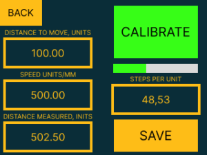
DISTANCE TO MOVE, UNITS: Set the intended travel distance for the calibration process.
SPEED UNITS/MM: Input the speed for the calibration move in units per millimeter.
DISTANCE MEASURED, UNITS: Enter the actual distance that the device has traveled during the calibration process for accuracy assessment.
CALIBRATE: Initiate the calibration sequence to ensure accuracy in movements.
STEPS PER UNIT: Displays the calculated number of motor steps per unit that the controller automatically determines by comparing the desired travel distance with the actual distance moved during calibration.
SAVE: Save calibration settings into the system.
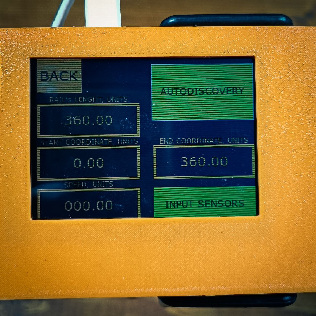
SETTINGS – RAIL
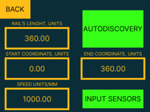
The AUTODISCOVERY feature operates on a straightforward principle designed to automate the measurement of the rail’s length. Here’s the process breakdown:
AUTODISCOVERY Activation: Upon pressing the AUTODISCOVERY button, the device initiates the calibration process by moving in one direction towards the first endpoint.
INITIAL ENDPOINT DETECTION: The device continues to move until it triggers the end sensor, marking one endpoint of the rail.
DIRECTION REVERSAL: After reaching the first endpoint, the device reverses its direction and travels towards the opposite end of the rail.
SECOND ENDPOINT DETECTION: The device stops upon triggering the second end sensor, which marks the other maximum point of the rail.
MEASUREMENT CALCULATION: Based on the distance traveled between the two endpoints, the controller automatically calculates and sets the rail’s length.
After the AUTODISCOVERY feature locates the second endpoint, the device will automatically return to the starting position, completing the calibration process. This ensures that the system is ready for precise operations from the designated origin point.
Additionally, the following settings can be adjusted:
SPEED UNITS/MM: Specifies the speed at which the AUTODISCOVERY process operates.
RAIL’S LENGTH, UNITS: Manually enter the total length of the rail if known, useful for setups like a rotary axis where the length corresponds to the degree of rotation (e.g., 360 units for a full turn).
START COORDINATE, UNITS and END COORDINATE, UNITS: Manually set the starting and ending points of the rail, which can be utilized when AUTO-DISCOVERY is not necessary or when working with preset limits.
For AUTODISCOVERY to function correctly, end sensors must be connected and activated within the controller’s settings, ensuring they are ready to detect the machine’s movement and set the rail’s length accurately.
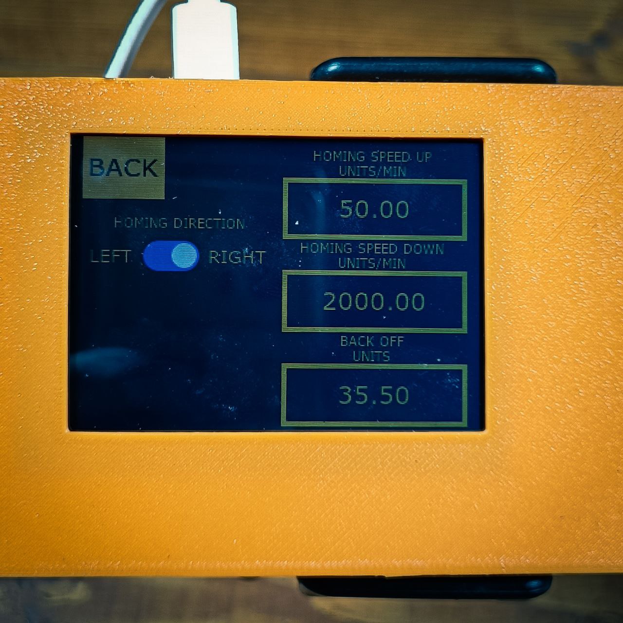
SETTINGS – PARKING
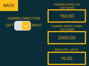
HOMING DIRECTION: Select the direction in which the machine should move to find the home position, which is marked by the end sensor also acting as the hard limit.
HOMING SPEED UP, UNITS/MIN: Set the speed at which the machine moves towards the home sensor.
HOMING SPEED DOWN, UNITS/MIN: Determine the speed at which the machine moves away from the home sensor after triggering it. This is set at a lower rate to fine-tune the machine’s position to the exact home location.
BACK OFF, UNITS: Define the offset distance the machine must travel away from the machine home to establish the working zero point. This offset ensures the start of operations occurs at a predefined position from the machine’s home.
MODE – SPEED
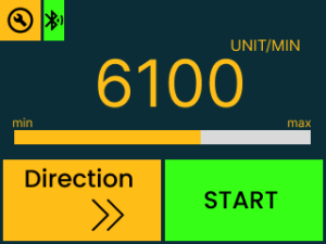
START/STOP Button: Press to start or stop the machine’s movement. This function is accessible via the on-screen button or can be managed with an external physical button. The external button uses a standard switch mechanism activated by a 5-volt signal for compatibility with various setups. For connecting external buttons, refer to the “External Button Connection Diagram” for proper setup.
DIRECTION Button: Alters the direction of the machine’s movement. This too can be controlled by an on-screen option or an external switch, facilitating quick directional adjustments during operation. It also operates with a 5-volt signal. Make sure to consult the “External Button Connection Diagram” for correct installation.
MODE – COORDINATE
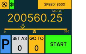
CONNECTION STATUS: Displays the controller’s connectivity status with an Android app or PC.
SPEED: Allows you to set the speed at which the machine will move during operations.
TARGET POSITION: The large number represents the target coordinate the machine will move to, which is input through a digital keypad that appears upon selection.
SCALE: Visual representation of the rail length, showing the current position and the target position where the machine needs to move.
START/STOP Button: Initiates or stops movement towards the target coordinate. This control can be executed through the on-screen button or via an external physical button, allowing for manual override or integration with external control systems. For instructions on connecting an external START/STOP button, please refer to the “External Button Connection Diagram.”
GO TO 0: Commands the controller to move to the established working zero at a designated parking speed.
SET AS 0: Defines the current position of the machine as the new working zero.
P (Parking): Indicates the need to perform a parking macro upon each startup to determine the machine’s position for accurate operation.
WIRING DIAGRAM


UPDATE FIRMWARE
If something goes wrong with your UPAN device, updating the firmware can often resolve the issue.
Follow these step-by-step instructions to safely update your device’s firmware:
Install STM32CubeProgrammer: The first step is to download and install STM32CubeProgrammer on your computer. This software is essential for the firmware update process.
https://www.st.com/en/development-tools/stm32cubeprog.html
Open the Controller’s Back Cover: Carefully unscrew the four black screws to remove the back cover of the controller. This will expose the internal components of the device.
Press the OT1 Button: Locate the OT1 button on the circuit board (refer to the photo for guidance). Press and hold this button down.
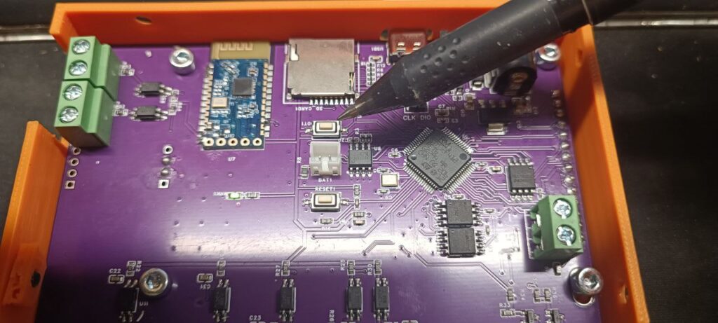
Connect the Device to Your Computer: While holding the OT1 button, connect the device to your computer using a Type-C cable. You should hear a sound indicating that your computer recognizes a new device.
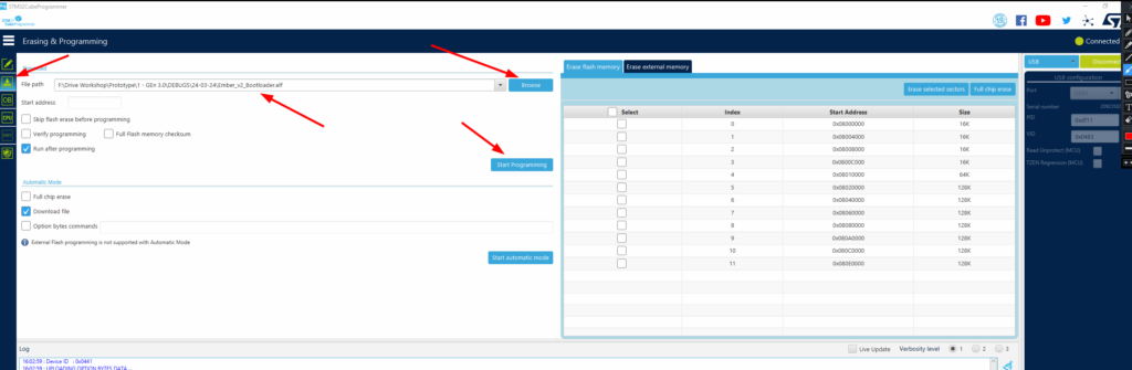
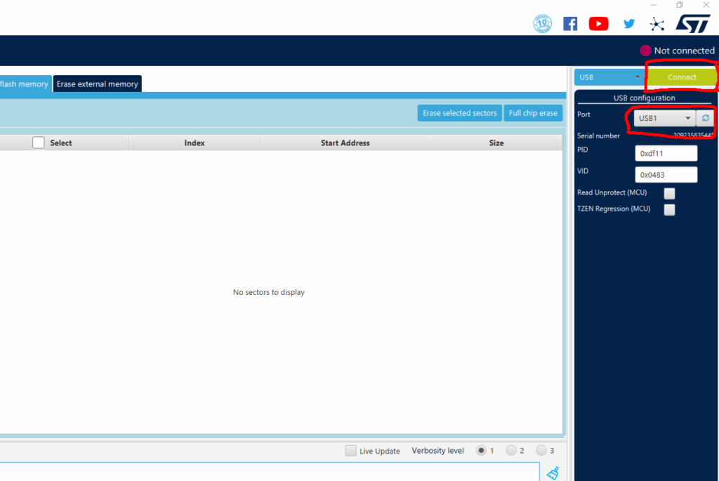
Launch STM32CubeProgrammer: Open STM32CubeProgrammer. In the upper right corner, you will find the “Refresh” button in the USB configuration section (refer to the photo for location). Click this button.

Connect to the Device: Once you see your device listed under the Port section as a recognized USB device, press the large green “Connect” button (refer to the photo for guidance).
Locate and Select the Firmware: Navigate to the location of the firmware file on your computer (refer to the photo for guidance). Select the file and proceed by clicking the “Start programming” button.
The firmware contains two files: the bootloader file and the firmware file. The bootloader file must be uploaded first.
Download Bootloader file UPAN-GEN-3.0_Bootloader
Download Firmware file UPAN-GEN-3.0-Firmware
After successfully uploading the bootloader firmware, you need to reboot the device with the Start/Stop or Direction button pressed (see the wiring diagram). If you’re not using external physical buttons, simply short these inputs with a metal object, such as tweezers.
![]()
If everything is done correctly, you will see the Bootloader menu on the screen (refer to the photo).
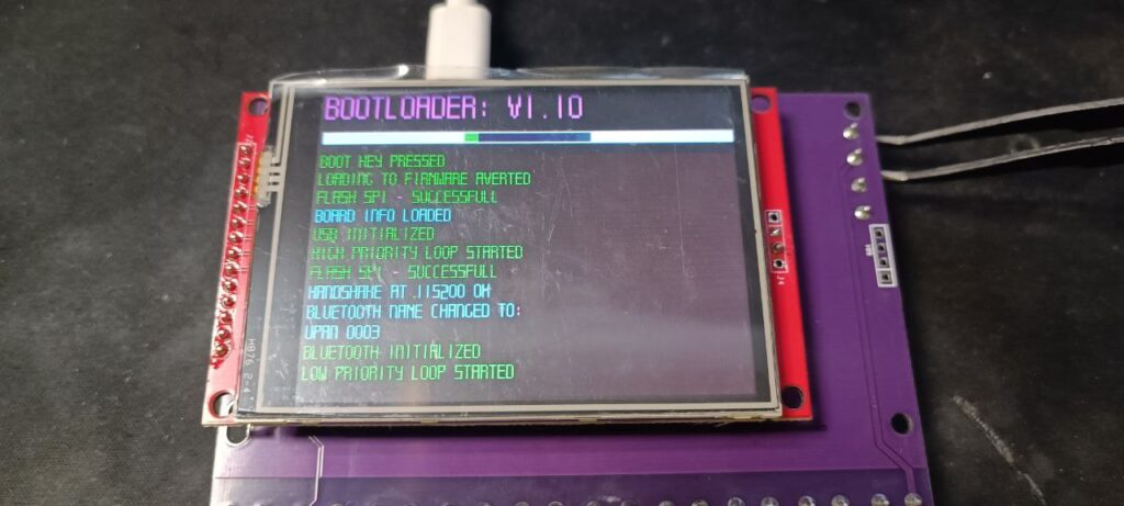
Carefully ensure there are no red warnings displayed, and that the Bluetooth name has changed to UPAN 0003. If not, press the RESET button on the back of the controller and without turning off the power, your controller will reboot. Should you still see entries in red (errors) after this, please contact us for assistance: info@cnc.house.
Important information: When pressing the reset button, you also need to press the Start/Stop or Direction button to re-enter the Bootloader menu.
⇓⇓⇓⇓⇓⇓⇓⇓⇓⇓⇓⇓⇓⇓⇓⇓⇓⇓⇓⇓⇓⇓⇓⇓⇓⇓⇓⇓⇓⇓⇓⇓⇓⇓⇓⇓⇓⇓⇓⇓⇓⇓⇓⇓⇓⇓⇓⇓⇓⇓⇓⇓⇓⇓⇓⇓
After installing the bootloader and initializing Bluetooth and USB, it’s necessary to install the main firmware of the controller.
Press the OT1 Button: Locate the OT1 button on the circuit board (refer to the photo for guidance). Press and hold this button down.

Connect the Device to Your Computer: While holding the OT1 button, connect the device to your computer using a Type-C cable. You should hear a sound indicating that your computer recognizes a new device.
Launch STM32CubeProgrammer: Open STM32CubeProgrammer. In the upper right corner, you will find the “Refresh” button in the USB configuration section (refer to the photo for location). Click this button.
Connect to the Device: Once you see your device listed under the Port section as a recognized USB device, press the large green “Connect” button (refer to the photo for guidance).
Locate and Select the Firmware: Navigate to the location of the firmware file on your computer (refer to the photo for guidance). Select the file and proceed by clicking the “Start programming” button.
Download Firmware file UPAN-GEN-3.0-Firmware
After you have uploaded the firmware to the controller, reboot the device in normal mode (WITHOUT pressing any additional buttons), and you should see the working firmware load up.

After the first boot, it’s essential to go to the settings menu and verify that all values have been recorded, such as the number of steps per unit or the speed.
ANDROID APP
Installing the Android App: You can download our Android application by following the provided link.